Share
Pin
Tweet
Send
Share
Send
In our arsenal there is an excellent homemade product that will delight masters who are more or less familiar with technology. I can’t say that this will take 5 minutes of your time and a pair of pliers with a knife, but there will be no higher mathematics either. All parts are budget and easily accessible. The installation itself is compact, mobile and does not even need to be connected to electricity!
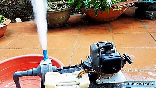
Now, let's all in order ...
Tool and accessories
The two-stroke engine from a moped, scooter, motorcycle may not necessarily be new. The author of the video collected his own version of the motor pump using an old engine from a chainsaw. The engine must be equipped with a starter, a carburetor, a muffler, a fuel tank and an electric starter (button). In addition to it we will need:
- PVC conical sleeve 90 * 34 mm;
- Crimp metal clamps of different sizes;
- Brass bushings flange;
- Drive shaft for models, thickness - 10 mm;
- A small sheet of aluminum, thickness - 1.5-2 mm;
- A piece of reinforced rubber hose, length 20-25 cm;
- External PVC plug, diameter - 90 mm;
- Angle 90 degrees PVC;
- PVC pipe, length - about 1 m;
- Threaded plastic adapter to the garden hose;
- PVC plug for gluing;
- Closed Bearing;
- Small piece of oxygen hose.

Instruments:
- Bulgarian (UShM) with a cutting disc for colormet;
- Drill with cutting and grinding nozzles;
- Screwdriver;
- Calipers;
- Protractor;
- Glue for bonding PVC compounds;
- Knife, tape measure, marker.
DIY motor pump
In the conical sleeve, from the side of the smaller diameter of the pipe, we insert an angle of 90 degrees, pre-coated with glue. We leave it aside, we will need this element later.

In order for the water to be pumped with a pressure strong enough for irrigation, centrifugal force alone is not enough. It is necessary to make the impeller of the pump, which will be its impeller. Let's make it from a sheet of aluminum. We mark the circle a few millimeters smaller than the inner diameter of the end cap, and cut out the angle grinder (grinder). At the transmission shaft, the end is slightly sharpened and has a diameter of 8.1 mm. We make a hole for it in the future impeller with a drill.

You can trim the circle by fixing its long bolt in the center and fitting it into the screwdriver. Turning it on and the grinder will turn out a mini-grinding machine))

We mark the circle into four parts with a protractor. With the help of some round object, for example, a small coil for solder, we draw the arcs of the impeller. With this shape of the blades, the pump efficiency will be much higher.

From the same sheet of aluminum we cut a strip about 15 mm wide. We measure approximately the length of the blades, and we end the strip into four segments. We bend them in the form of drawn arcs.


We put a circle on the shaft, and weld it with MMA or tungsten electrodes for aluminum, using reverse polarity (for inverters). The seams from the semiautomatic device and the wire will be much more accurate.


We also fix the impeller blades, distributing them according to the marks on the aluminum circle. If there is no welding, it may help out a soldering iron and special fluxes with solders. We cover the finished scalded shaft with an impeller, protecting it from oxidation and corrosion (a car spray is best suited).


Using a pen drill on a tree of 14 mm, drill a hole in the PVC end cap. Wearing a brass sleeve in it, the scalded end of the shaft will rotate freely during operation of the pump. We fix it on glue for PVC.

We place the threaded adapter on the hose on the side wall of the housing of the end cap. In order for the water supply to go without obstacles, it must be fixed at an angle. We cut the thread into an oblique, and make a hole under it with a 15 mm feather drill in the plug. You can give it an oval shape by working with a knife, a round file or a drill with a grinding nozzle. After fitting the adapter, glue it with glue or cold welding to the plug (the connection must be strong and tight).


For PVC couplings, we cut a wide ring to the collar line and a narrow ring, removing an angle of 90 degrees. From a short trimming of the pipe, we make a direct adapter for the intake pipe or hose, and glue it.


Next, we drill a hole in the plug for the insert for the motor shaft. We insert a sealed bearing into it, which we selected for the shaft diameter.


We put the plug with the bearing on the pump housing, with the help of the shaft we center it and glue it.

We cut the excess with a hacksaw for metal.
On the shaft rod we make a notch with a dremel under the circlip, it will not allow the bearing to shift during operation.

We cut the rod with a grinder, leaving a length of approximately 100-150 mm. This size depends on the distance from the pump to the motor. For long-term trouble-free operation of the pump, it is necessary that the shafts of the working part and the motor are at a minimum distance. Through the gasket, we put the shaft with the impeller in its place in the pump housing, and put on the circlip.


We glue the rest of the - clutch cut under the collar. The working part of the pump is ready, it can be checked by inserting a shaft rod into the screwdriver chuck. If everything is assembled correctly, there will be no friction of the impeller against the walls of the casing.

For the bed, select a board wide enough in width. It must be stable and level so that the equipment can be accurately installed. It will not be superfluous to paint it in order to protect it from moisture.

We expose the pump on the bed so that the shafts of both working segments are in contact, and try on the mounting clamps. The shafts should be maximum on one line so that the difference between them does not lead to backlash, excessive vibration and wear of the equipment. From the oxygen reinforced hose, cut out the connecting braid for the shafts, and put on the crimp clamps.

After making sure that all connections are suitable in size, we fix the pump and motor to the bed with self-tapping screws. The rubber hose on the shaft is crimped with clamps.
From one of the sides we catch the fuel tank. We fix it on a long dowel screw, and we bring the fuel pipes to the engine.
From the back of the wooden bed at four corners we wind the shock absorbers from the rubber tires folded into several layers. So our pump will be less noisy during operation.
The start button is brought out so that it is convenient to turn on the pump by hand. Fill the fuel mixture into the tank, and make a dry test run of the pump. You can immediately adjust the fuel supply to the engine, and the intensity of its work.

Now it remains only to bring the intake pipe to the pump. It can be made from a regular water or garden hose, and connected through an adapter with a clamp. The author chose to glue an additional removable elbow from the PVC pipe and fittings.
Well, put a container of water and check how it works?
We start the engine and set the idle speed so that the centrifugal clutch is put into operation. To start any centrifugal pump, it is required to initially fill the water into the outlet pipe to remove air, and then the pump will start working on its own.

Everything functions perfectly, and even under what powerful pressure!


With such an installation, you will once and for all forget what drought is in your personal plot. Good luck to everyone and a good harvest!
Share
Pin
Tweet
Send
Share
Send

